Friday, March 13, 2009

Pulled the motor out today!

But first, we still needed to free the front springs. After over an hour of unsuccessful attempts last time, Marc decided the only way we were gonna get the spring compressor into the front springs would be to get the struts out of the way.

And those were on pretty tight, so we had to bust out the torch:

With that, the nuts broke easily, and we finally got enough vertical space to put the compressor rod on. Even so, we could only grab a couple coils, so it wasn't enough to compress the springs. Since we already had the lower control arm jacked up for safety, Marc said it screw it and started lowering the control arm. It was risky but we were standing as far out of the way as possible. Fortunately, the springs unloaded and fell out.

We recovered all the bits for the Maximum Motorsports camber plates setup. CG'll be able to thrown that on CL for a small sum.

Then we got down to the big ticket item. Ben brought the company engine hoist over, which was a good money saver for the project. We fumbled around looking for the mounts on the engine block for the hoist. This was pure winging it, and fortunately, it worked out -- the 5.0 has threaded holes on the front and back of the block. On the front you have to unmount the power steering pump, and on the rear, I think it was just free holes. Even so, they were so close to the firewall it took me like 10 minutes to get one side off, my elbow slightly hyperextended the whole time. So we ended up with 2 chains on the front and one in the back.

Raise that sucker up:

Minor wrinkle was a pair of grounding wires on another rear bolt, even less accessible. After confirming the engine and tranny were in fact clear of all other wires, I unbolted it and we were ready to take it out.

We tilted the nose up to get the tranny out of its tunnel.


The 8-ton hoist didn't have as much vertical range as we needed, so we had to lower the front jackstands under the car to dip the radiator support so we could get the oil pan over it.

Not pictured is the engine and tranny sitting on two race tires (we haven't figured out how to put the engine on the generic engine stand). It leaned to the side about 20 degrees and puked out about a quart of coolant. What a mess.

And finally, the empty engine bay:


Note to self: where are the endlink bolts for the steering rack?

Monday, February 16, 2009

pics from last Thursday

Don't have much to add that CG didn't already say. But here are some pics from this awesome sessions. I am fueled to press on by visions of tearing around cones at an autocross with the finished product.


The intake manifold off and set aside. No one step on the throttle body!


Engine bay now. All the wires are off and we plugged up the block.


A shot down into the engine bay. You can see the troublesome steering shaft in the very middle of the picture, to the right of the trouble light.


Front sway bar. Note: we're missing a nylock bolt for the top of one of the endlinks. The bolts to the sway bar mounts are also really rusted and rounded.


Steering rack. You shoulda seen how bad the power steering fluid is.


The Foxbody front suspension is the devil. We have yet to get the springs off. At least we have the right tool now.


The rear springs, howewer, are down and out.


You can see the quad shock finally unhooked in the center of the picture there. The rear is coming apart fast.

Saturday, February 14, 2009

Back in the shop again...

Winter in New England means snow, cold, bad roads, bad drivers (ok that's a constant), cold, and snow.  And did I mention cold?  The garage has been freezing cold all winter, and it's been difficult to get enthusiastic about working on the car.  Whacking your knuckles on hard metal is painful, with code hands it's far worse.  Whine, whine, whine...

So finally on Feb 12 we got together to work on the car.  We're still tearing down the Mustang, and in November it felt like we had 8 things 40% done.  After wrapping up Thursday night we're a whole lot further down the road and it feels like we're finally making some progress.

The wiring harness is nearly completely disconnected from all things in the engine compartment.  The intake manifold is off the engine in preparation for removing the engine.  The hard lines are off the power steering pump, and the rack is out of the car.  The front and rear sway bars are removed.  The rear springs are out of the car.  The quad shocks are disconnected.  Most of the panhard bar is disassembled in place.  The rear end is almost out of the car.  We need to disconnect the driveshaft and a few remaining pieces of the panhard bar and then the rear will be separate. 

Looking at the current status, it would seem after one more good session like this we'll be able to remove the engine fro the car and get it on a stand for inspection and possible tear-down.  Once the rear-end is out I can start cleaning it up and getting it ready for paint.  I'm personally looking forward to getting on to the actual build of the new car, and will be happy when we can get the Mustang chassis out of the garge and sold.

So all-in-all, a great night working in the garage.  The 4 of us got a mountain of work done in less than 5 hours, and it was a lot of fun to get my head out of the office and computers and into the shop.

Monday, November 3, 2008

11/2 update

11/2 update:

For his bday, CG got the gift of a whole day of working on the car in the garage.

Picking up right where we left off, I tackled pulling apart brake booster and master cylinder. It took a while to unravel this intricate puzzle, but I finally managed. I unbolted the MC's union fittings into the distribution block, so that the brake booster and MC were free. After that, I was able to wiggle them out of the car. With some difficulty, I was able to unbolt the MC from the booster. Unfortunately, I totally destroyed one of the bolts. Need to get a replacement.

The instructions for making manual braking are to fit the brake pushrod directly into the master cylinder piston. Problem is, with the Cobra brake kit, the huge pushrod seems to have a much huger diameter than the piston into the MC. Will need to follow up with FFR to see what's up. Maybe we can buy a pushrod from them.

I sawed the distribution block's brake lines free of the body and recover it as well. The instructions are vague but I think we won't need these lines and will be fitting on parts from the kit.MC and distribution block socked away for now.

Next job for me was starting on the engine wiring harnesses. This was a real pain. Plastics were really brittle, many connectors had their latches on the blind side or hidden, and fasteners were rusted. Still a custom harness from FFR is $475, so this would save a lot of money.


I tackled the driver's side harness first. It seems to have more of the wires powering non-motor devices and distributes the +12v source from the battery mounted in the hatch. Lots of the looms wormed into fender undersides and had to be rooted out.

While I was down there unscrewing the horn and pulling out headlight wires, I found a piece of clag (tire debris) wedged high up into the fender edge. All over the engine bay were chunks and strings of clag. Truly a well worn race car.


All of the left harness was unraveled and labeled. The only thing left attached on the left harness network is 2 plugs into the alternator. I was wearing thin and snapped the latch off of the sensor plug. I think the alternator might have to be loosened or removed to get clearance to pull it off. Any 5.0 guys know?

CG and Marc were working on the suspension, panhard setup, and exhaust. It was an ugly ground war against rust and tack welded nuts. They managed to get the sway bar and one rear strut off. Oh, and the X-pipe. Very clean and quite a sculpture after 10 years on the car.

We also got the radiator, fan, and air filter out.


Next:
- loosen rear diff and axle to unload left rear suspension
- plasma cut through some of the quad shock assembly (I dunno what happened back there but I think we ran out of alternatives). Fortunately CG got the upgraded suspension parts so we won't need to reuse that stuff.
- disassemble rest of suspension
- proceed with wiring harness extraction. I need to get all the motor wiring off, and then work from the dash to the back of the car.
- steering rack
- rear diff off
- engine out (maybe with an optional test crank that we keep putting off)


Some wisdoms I gained from doing the wiring harness work. I dunno if it's applicable just to 5.0s or more Fords.
- the lightbulb wiring plugs unlock by twisting counterclockwise, except for the main lights. They have a collar that twists to unlock. Move that out of the way and then there's a latch that comes off with the plug. Once unlocked you can pull them straight out.
- when working with the lights, hands go in through the gaps in front of the radiator bracket.
- remove the light wire looms through the central hole in the radiator bracket that the main wiring loom passes through. All the plugs even with the bulbs on them will be able to snake through. I recommend taping up the bulbs for that extra sense of protection.
- the airbag sensor needs to be pulled out through the same front gap where your hands fit. By god it is a tight fit but it'll work. You might have to unhook the main headlight plug to get clearance. The ABS sensor's loom has a plug further up the harness. To get it out, unplug there and pull that part of the loom through the hole following the sensor's exit.
- the airbag sensor looks like a little transformer mounted under the top of the radiator bracket, but with 2 wires leading to it.
- when disassembling stuff, get into the assembly line frame of mind. Each part should have one clear (if not easy) way of getting installed. If it isn't going to go out one way, keep looking for the correct way. Order matters in that some parts get installed later and can 'lock in' earlier parts.

Monday, October 20, 2008

update 10/19

click on the thumbnails for big.


We finally gave up and drilled out the stuck nut on the strut brace. That might net us $50 from a Foxbody enthusiast. We originally wanted to get it out to be able to oil the cylinders and test if the engine would rotate. But we decided it didn't need to be done now since the test was quick and we'd have plenty of time to rebuild it or source a new engine later.


Ben from Terrafugia disassembling the steering column. It mostly went ok, but the instructions said we could pull the spline shaft free from the steering rack. This wasn't the case for us, so we undid the next U-joint towards the steering rack and pull everything up to that half of the U-joint through the firewall. Note for the FFR manual: there could be a lot of loose single wires that the steering column mounts could snag on, so make sure you have clearance before you try to tug it out. We still have to remove the sleeve around the steel column shaft, as the kit doesn't need it. Oh, and the U-joint half needs to go with the steering rack, not here. Just to stick to the instructions.


Steering wheel and column out of the car. Note CG's aftermarket tach and shift light. His speedo cable broke, so we'll have to buy one as a donor part for the kit.


The ECU. This was hell to get out because it was packed between the rollcage and the fender wall. It was a slow process of unsnapping plugs and unbolting the ground. This thing better still be working, dammit.


Shot of the opened up Mustang. When we first tried to do either the ECU or steering column, we found the tight bucket seats to be a huge pain to work around, so we unbolted those and took the doors off. Oh, and also removed those roll cage foam pads, since the zip ties ends kept stabbing us as we got in and out.


The Mustang is nice and boxy, so perfect to storing stuff on.


the racing seats with their covers removed. Not sure what the plan with these is. The kit came with some seats and harnesses of their own.


Steering column and brake pedal washers. We were halfway done with removing the brake booster and master cylinder and decided to call it a day. But we at least unhooked the brake pedal from the brake booster pushrod. The instructions emphasized remembering the order of washers and clips mating the pushrod to the pin on the brake pedal, so I drew a diagram and ziptied them in order.


Misc crap sitting on the intake manifold.

It was a good 3 hour session. We were pretty on target time budget-wise with the donor part removal steps, but didn't account for taking out the seats and doors.

Next steps, roughly in order:
- bleed out brake fluid before removing MC and brake booster (I don't think the instructions reminded us to do it)
- remove brakes
- remove brake booster and MC
- remove steering rack
- extract wiring harness (will be a royal pain in the ass)
- rear end, suspension elements, e-brake
- headers, engine and tranny

Tuesday, October 14, 2008

Delivery Day

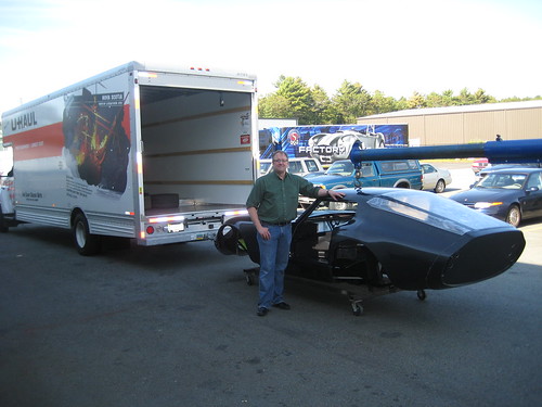
On Tuesday 14-October we took delivery of the Factory Five kit. This was a really fun day, as I traveled to the Factory Five factory in Wareham, MA with a UHaul to pick up the kit.

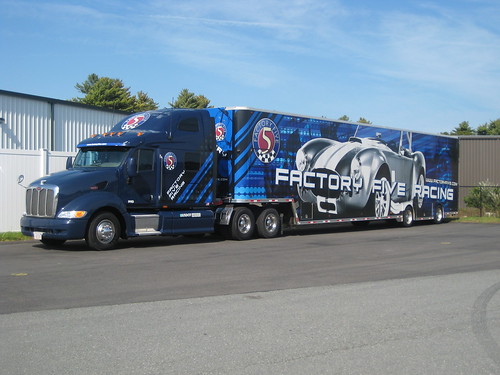
The Factory Five World HQ is located in a somewhat non-descript facility at the end of the road in an industrial park. I was pretty sure I had arrived when I hit the cul-de-sac and the pavement was full of skid marks. This transporter pretty much gave it away too:


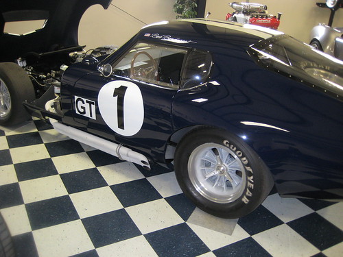
The showroom has really stunning examples of the various models sold by Factory Five. I was particularly excited to see the Type 65 Coupe close up. I’ve seen one running example of this car on the street (for about a minute as the guy motored away), and I’ve seen the Factory Five DVD. But it wasn’t until Tuesday that I actually put hands-on the car itself:


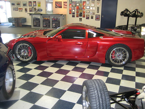
There was also an excellent example of the GTM Supercar. I’m very interested in building one of these some day. We’ll have to see how the Coupe build goes first, but the GTM is an amazing car.


I met with Jason Lavigne, who gave me a tour of the facility. It’s a very cool place – a combination of straightforward and sophisticated, industrial and high tech. Everybody there is fired up about cars and racing and downright friendly. Judging from all the build blogs out there Factory Five must be one of the most photographed factories in the country. Nobody seemed to mind as I snapped pictures during the tour.

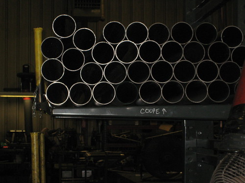
Stack of main tubes for coupes:


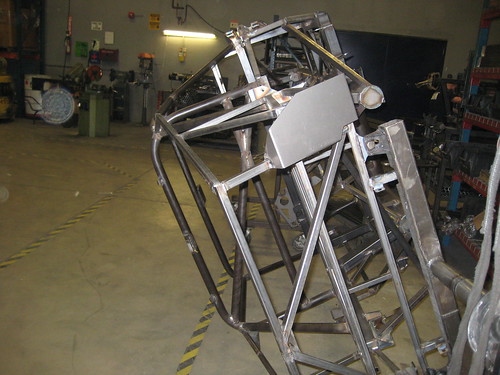
Vehicle chassis on rotating frame:


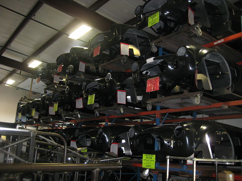
Roadster bodies stacked up:


Aluminum panels ready for use. These are pre-shaped, with cut-outs, and ready to go:


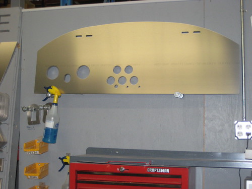
Coupe dashboard panels:


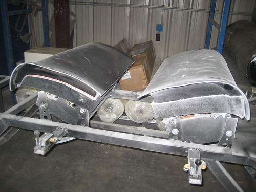
Coupe doors under construction:


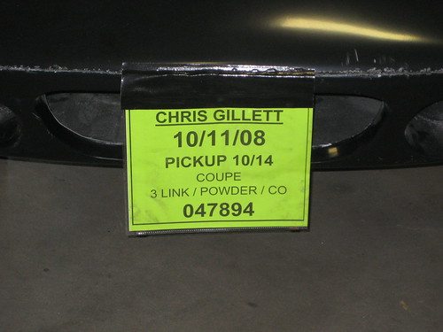
After touring the facility and meeting people at Factory Five it was finally time to meet the kit. It sounds corny, but seeing this sign attached to the body of my kit was really exciting:


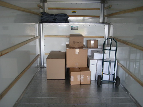
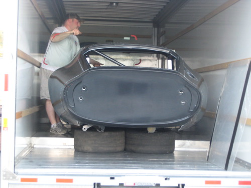
Next it was time to load the kit into the truck. Here’s the stack of boxes on board:


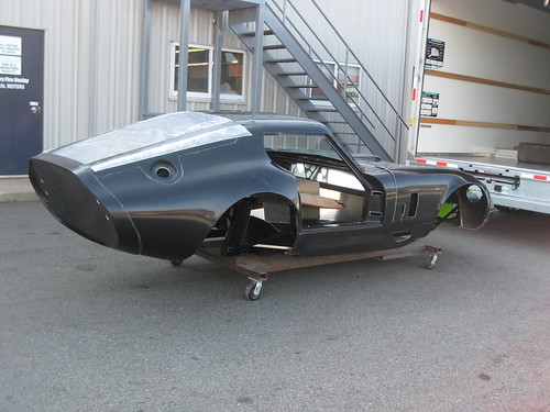
Here is kit, on a rolling frame, ready to go on the truck:


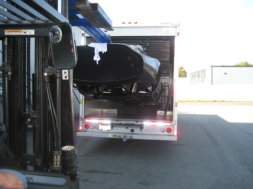
When you pick up the kit the body is on the frame, and several of the aluminum panels are on the frame. The windshield and rear glass are taped onto the body. In order to load the car the guys removed the windscreen and rear glass, and then guided a boom into the cockpit. This allowed them to raise up the car by the roll hoop and put it in the truck.


Once I got the kit loaded, I headed back to the showroom to take some technical photos of the front suspension. As I looked around, Dave Smith (President and founder of Factory Five) wandered over and introduced himself. This led to a great discussion of chassis setup, car philosophy, etc. He showed me the Roush Coupe, which can be seen on the Factory Five web site photo gallery. Dave is a committed racer and passionate about cars, and really seems to enjoy his job. Meeting him was totally by chance and was pretty neat.

With the truck loaded up I stopped a nearby Lowes and bought some tie down straps to secure the chassis for the ride home. Then I headed for home to unload.

Meng and Marc came over to help unload the car. The photos we took of the off-loading process did not come out, which is unfortunate. Sufficient to say, however, you really want 4 (or maybe even 6) people to help out with the unloading process. The 3 of us struggled a bit, but ultimately we got the body off the chassis, the chassis into the garage and on stands, the boxes into the garage, and the body propped up on wood outside in the driveway.

Friday, October 3, 2008

Craftsman Tools

I mentioned in an earlier post that I had picked up some more tools for this build.  I used some gift cards and bought a Sears Craftsman 260 piece mechanics tool set.  It came with a "free" 3 drawer plastic tool box that I originally thought would be useless.  Instead I was pleasantly surprised.  Each of the 3 drawers is fully removable from the box, and holds the sockets and drivers for 1/4", 3/8", and 1/2" sized ratchets respectively.   The size of each socket is molded into the drawer which makes finding the right size easy.  Best of all, you can carry the drawer to the work site easily, which makes locating the right size socket while in an inconvenient location (like under the car) much simpler.

I've always been a fan of Sears tools, and this set continues to keep me a fan.  Now I just need a couple cabinets and a few more air tools and the shop will be well equipped.